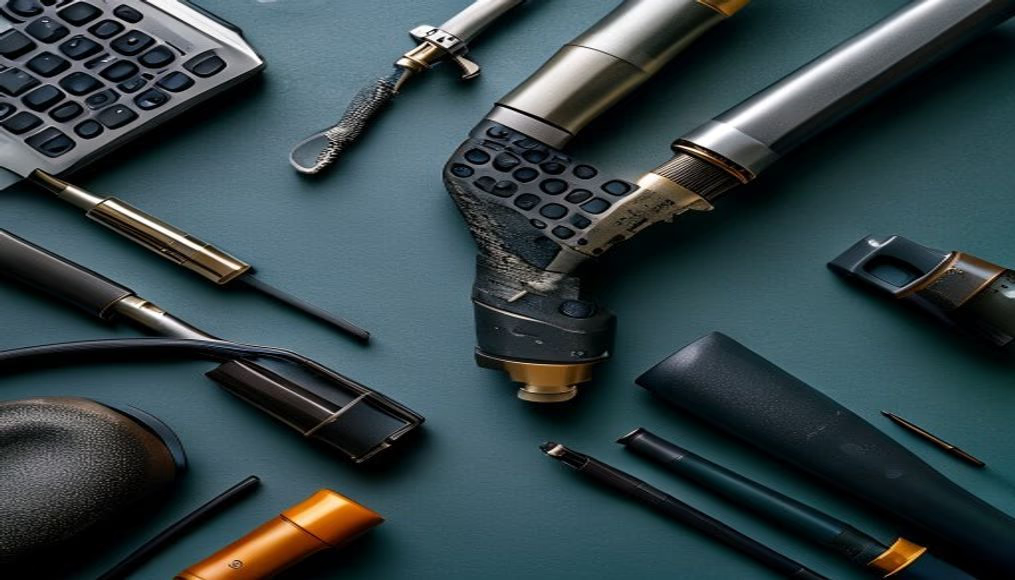
Circuit traces pcb closeup
1344×768 · AVIF · CC BY 4.0

Microscopic details of copper traces on a printed circuit board (PCB) reveal the electronic engineering that enables devices like disposable cameras to function.
About this subject
On a printed circuit board (PCB), copper traces are extremely thin conductive paths that interconnect electronic components such as resistors, capacitors, and integrated circuits. Manufactured through chemical etching or milling, these traces follow a layout designed in CAD software, optimized to minimize interference and signal loss. In disposable cameras, the PCB manages functions like flash firing, exposure, and film advance, using simple and durable analog circuits.
Typical trace thickness ranges from 0.1 mm to 0.3 mm, and the spacing between them is critical to avoid short circuits. In the context of low-cost cameras like the Lo-Fi Disposable Camera, the PCB design prioritizes manufacturing efficiency and mechanical strength. Many such cameras use phenolic paper boards (resin-impregnated paper), cheaper than fiberglass, with gold-plated contacts to prevent oxidation.
Historically, component miniaturization and the advent of double-sided PCBs allowed disposable cameras to shrink in size starting in the 1980s. Surface-mount technology (SMD) replaced through-hole components, although very simple cameras still use manually soldered traditional parts. Close-up photos of exposed traces reveal the path of electric current from the battery to the flash capacitor, which generates high voltage to illuminate the scene.
Interestingly, the lo-fi aesthetic of such images, grain, desaturated colors, chromatic aberrations, contrasts with the precision of the internal circuits. The juxtaposition between rugged industrial design and fragile trace details highlights the hidden complexity in seemingly simple objects.
Frequently Asked Questions
What is the function of copper traces on a PCB?
Copper traces are conductive paths that electrically connect electronic components on a printed circuit board, enabling signal and power transmission.
Why do disposable cameras use phenolic paper PCBs?
Phenolic paper is a low-cost, easily drilled material suitable for mass production of disposable devices, though it is less robust than fiberglass.
How does trace design affect a camera's performance?
Trace layout determines signal integrity, heat dissipation, and noise immunity. In disposable cameras, a simplified design targets basic functionality at minimal cost.
Direct URL
https://pub-c7d6a6ea828543ac903a74a341ccb2e1.r2.dev/imagens/circuit-traces-pcb-closeup-lo-fi-disposable-camera-p3.avifHow to credit
Include a visible link back to UtilizAí. Copy one of the snippets below:
<a href="https://xn--utiliza-eza.com/en/midia/imagens/circuit-traces-pcb-closeup-lo-fi-disposable-camera-p3">Circuit traces pcb closeup</a> by <a href="https://xn--utiliza-eza.com">UtilizAí</a>, licensed under <a href="https://creativecommons.org/licenses/by/4.0/">CC BY 4.0</a>.
[Circuit traces pcb closeup](https://xn--utiliza-eza.com/en/midia/imagens/circuit-traces-pcb-closeup-lo-fi-disposable-camera-p3) by [UtilizAí](https://xn--utiliza-eza.com), CC BY 4.0
License: CC-BY-4.0