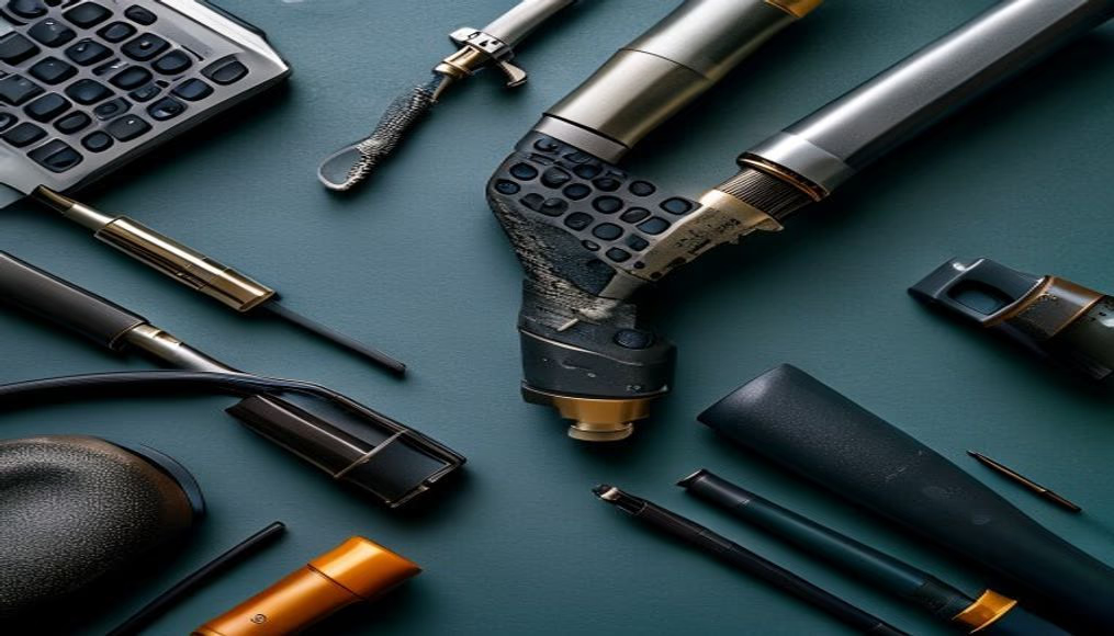
Circuit traces pcb closeup
1344×768 · AVIF · CC BY 4.0

Close-up of circuit traces on a printed circuit board (PCB), showing the intricate copper pathways connecting electronic components.
About this subject
Printed circuit boards (PCBs) are the physical foundation of most modern electronic devices. The circuit traces, fine copper pathways etched onto the board surface, form the electrical connections between components such as resistors, capacitors, and integrated circuits. The precision of these traces is essential for the correct operation of devices like smartphones, computers, and medical equipment.
The PCB manufacturing process involves photolithography and chemical etching. A copper layer is laminated onto an insulating substrate, typically FR4 (fiberglass with epoxy resin). A photoresist mask protects the regions that will become traces, and the unprotected copper is removed by chemical etching. Typical trace widths range from a few micrometers to millimeters, depending on current requirements and component density.
Historically, PCBs were invented by Austrian engineer Paul Eisler in the 1930s but became widespread only after World War II. Before that, connections were made with loose wires (point-to-point wiring). With miniaturization, multilayer boards emerged, where several layers of traces are interleaved with insulators, allowing complex circuits in small spaces.
Interestingly, trace width and spacing are critical design parameters: very thin traces can overheat or break, while traces too close can cause shorts. In high-frequency circuits, such as router boards, trace length and impedance are calculated to avoid signal loss. Continuous improvements in manufacturing now allow trace widths below 10 micrometers, enabling processors with billions of transistors.
Frequently Asked Questions
What are circuit traces on a PCB?
They are copper pathways that conduct electricity between components on the board. Their thickness and width determine the supported current and electrical resistance.
How are circuit traces manufactured?
Using photolithography and chemical etching. A photoresist mask protects the desired areas while excess copper is removed by chemical etching.
Why is trace width important?
Width affects resistance and current capacity. Very thin traces can overheat or break, while very wide traces waste space.
Direct URL
https://pub-c7d6a6ea828543ac903a74a341ccb2e1.r2.dev/imagens/circuit-traces-pcb-closeup-documentary-photography-p9.avifHow to credit
Include a visible link back to UtilizAí. Copy one of the snippets below:
<a href="https://xn--utiliza-eza.com/en/midia/imagens/circuit-traces-pcb-closeup-documentary-photography-p9">Circuit traces pcb closeup</a> by <a href="https://xn--utiliza-eza.com">UtilizAí</a>, licensed under <a href="https://creativecommons.org/licenses/by/4.0/">CC BY 4.0</a>.
[Circuit traces pcb closeup](https://xn--utiliza-eza.com/en/midia/imagens/circuit-traces-pcb-closeup-documentary-photography-p9) by [UtilizAí](https://xn--utiliza-eza.com), CC BY 4.0
License: CC-BY-4.0